It is the pool builder’s job to make the client happy and to help them realize their dreams of having a backyard oasis, which is an important aspect of pool construction. However, the most important part of pool installation is what is below the ground and how it affects the look and functionality of the final product.
Correct plumbing design, pump selection, and optimal flow rates are extremely important to ensure proper flow in a pool system. This is especially true in today’s pools that often have spas, water features, and vanishing edges. Pool professionals can also increase the energy savings with properly sized plumbing and pumps.
The importance of plumbing schematics and pump sizing
Although every pool design is different, the basics of hydraulics are the same. Water needs to be drawn from the pool, pumped through the mechanical system, and returned to the pool. All circulation loops are made up of different types of energy—pumps convert electrical energy into potential energy (elevation head), kinetic energy (flowing water), and pressure energy (to overcome friction, minor loss, and component loss). By looking at the energy of the system, pool professionals are able to use the information to devise an energy-efficient circulation system and select the appropriate pump for the application.
Plumbing design
Plumbing design is important to reducing friction loss. Pipe size, length of run, and flow rate all play an integral role in determining the amount of friction loss. If the pipe length doubles, the friction loss doubles, as the pipe diameter decreases, the friction loss increases significantly, and if the flow rate doubles, the friction loss quadruples. It is these reasons why pump sizing and piping design play a major role in the efficiency of the overall design. Plumbing fittings account for some friction loss, which are considered minor, while the filter and heater contribute as component losses.
The losses described above are expressed in values of total dynamic head (TDH), which is the head the pump needs to generate when it is running to overcome these losses. Pool professionals also need to consider the total static head, or the difference in elevation between the pool and the pump, when calculating TDH. By calculating the TDH, it enables the use of the manufacturer’s pump curves to select the correct system for the pool.
Before calculating the TDH, a few basic assumptions are made and a plan for the plumbing design is created. To do this, the desired flow rate must be found first. For an average residential pool, a 12-hour turnover is generally sufficient. Assuming a 120,000-L (31,700-gal) pool at a 12-hour turnover (120,000 L / 3.8 gal / 12 hours / 60 minutes = 166.5 litres per minute (lpm) (44 gallons per minute [gpm]) for the pool’s flow rate.
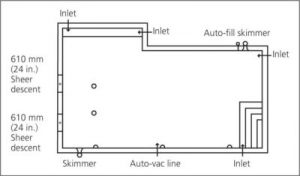
Figure 1: Pool Layout
Once the architect provides a plan for the pool (see Figure 1), the skimmers, drains, and returns can be located in a manner that will optimize circulation, while also taking esthetics and accessibility into account.
When placing a skimmer, be aware of prevailing winds. Placing the skimmer in a location where it will collect debris when blown by the wind will assist in skimming surface debris from the water. Returns must be placed in such a way to allow the pool to direct water towards the skimmers, while also reducing dead spots (i.e. stagnant areas) in the pool.
In designing the plumbing layout, the flow must be balanced between multiple return inlets and suction outlets. For pairs of suction outlets, one line must be capable of handling the full rate when one is blocked, so the design will need to allow for full flow from each outlet. Pipe sizing should also be selected at this time. The maximum flow of a return line should be designed at 2 m/s (6.5 feet per second [fps]) and 1.4 m/s (4.5 fps) for suction piping. See Table 1 for the max flow rates for schedule 40 polyvinyl chloride (PVC) pipe.
In choosing the line sizes, the full flow for each point of suction should be used. This means it requires 166.5 lpm (44 gpm) for the skimmer and main drain lines. If there are multiple skimmers, the flow should be split between them, but do not go lower than 50.8-mm (2-in.) pipe to minimize the chance of plugged lines. Using Table 1, choose 50.8-mm (2-in.) pipe. This provides 178 lpm (47 gpm) at 1.4 m/s (4.5 fps). For the returns, Table 1 shows 38.1-mm (1.5-in.) pipe can be used.
Should the pool include water features in its design, such as two, 0.6-m (2-ft) sheer descent waterfalls that are 0.6 m (2 ft) above the water level, with a desired projection of 0.3 m (1 ft) from the wall, the flow rate should be between 151.4 and 181.6 lpm (40 and 48 gpm). Therefore, a 50.8-mm (2-in.) pipe will be sufficient for the suction and return lines.
The main drains will be drawing for the circulation pump (166.5 lpm [44 gpm]) and the sheer descent pump (178 lpm [47 gpm]). With a total of 344.5 lpm (91 gpm) being drawn from the main drains, 76.2-mm (3-in.) pipe coming from the drains is required.
Determining TDH
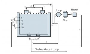
Figure 2: Pool Plumbing Plan
Knowing this information, TDH can be calculated as follows:
- Sketch the plumbing plan (see Figure 2) and label the starting and ending points of each segment. The segments are the pipes, fittings, and components between each point. It is best to start at the suction points and end at the return points.
- Set-up a calculation table or spreadsheet.
- In the table, start with a suction point and label the segment and starting point and pipe size. Note the total length of the pipe, type, quantity, and equivalent length of the fittings (see Table 2). Calculate the total equivalent length for each diameter and calculate the sum of the pipe and equivalent lengths for each.
- Calculate the head loss for each equivalent length of pipe and fittings.
- Enter the component head loss as found in Table 4.
- Complete steps three to five for each segment and calculate the head losses for each.
- For parallel segments, compare the total head and discard the lowest head segments.
- Add the total static head. Consider it as a segment between the highest discharge water level and the lowest suction level. If the pump is pulling from a skimmer, assume the water level in the skimmer.
- Sum the head of each segment, ignoring the discarded parallel segments. This is the TDH. Once this has been determined, the right pump can be selected that matches the flow rate and TDH.
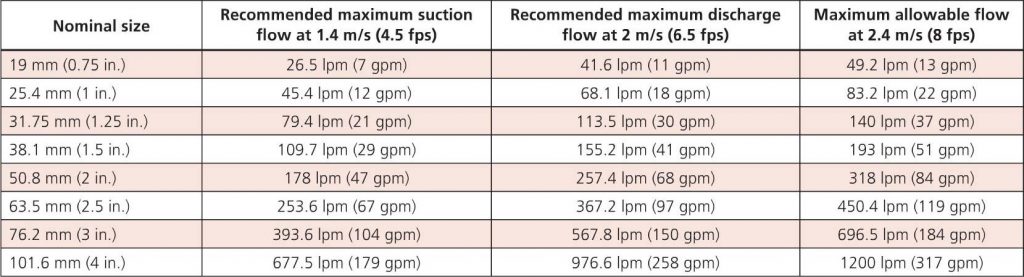
Table 1: Specifications for schedule 40 PVC
![Table 2: Friction loss through fittings (equivalent pipe length in m [ft])](https://asapponline.com/wp-content/uploads/2017/11/Plumbing_Table_3-1024x377.jpg)
Table 2: Friction loss through fittings (equivalent pipe length in m [ft])
![Table 3: Component losses (metre[feet]) of head](https://asapponline.com/wp-content/uploads/2017/11/Plumbing_Table_5-1024x570.jpg)
Table 3: Component losses (metre[feet]) of head
Today, with more variable-speed pumps being installed on residential pools, flow rates must be considered a little differently. Throughout a 24-hour period, the system will still need to turn over the water volume at least two times. Notice in Figure 1, the 166.5 lpm (44 gpm) at 15.2 m (50 ft) TDH will operate around 2750 rpm. To reduce electrical consumption, the pump should be programmed to operate at half of the design speed during the peak and mid-peak electrical hours (12 hours) and one-and-a-half the design speed during off-peak hours (12 hours). This means the design will revolve around a 250 lpm (66 gpm) flow rate.
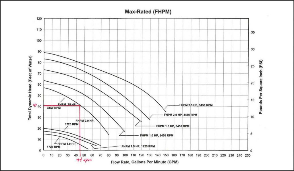
Pump Curve 1
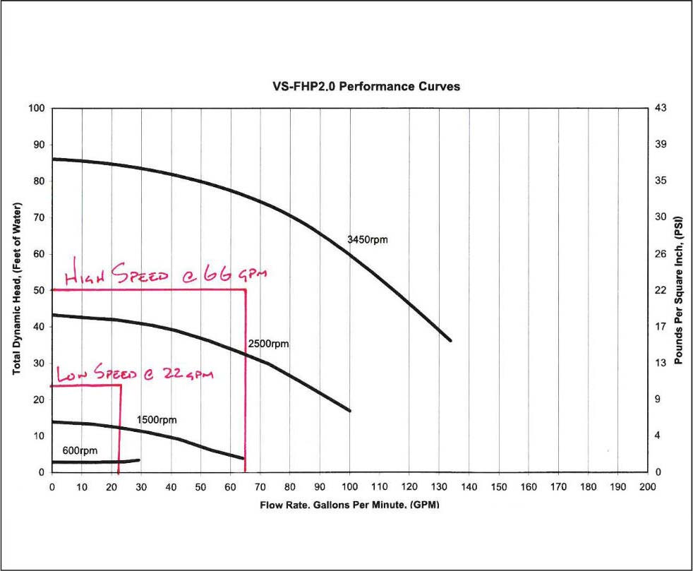
Pump Curve 2
Using the original piping design to calculate a TDH of 15.3 m (50.3 ft) of head at 250-lpm (66-gpm) and a TDH of 7.28 m (23.9 ft) of head at 83.2 lpm (22 gpm), it becomes clear where the pump speeds can be set to achieve the desired 12-hour turnover throughout the day.
The process of planning and designing the piping and mechanical systems before commencing a project will provide the client with an efficient mechanical system that will save them money in electrical costs and chemicals.
This article was written by Melissa Brown and originally appeared on Pool & Spa Marketing [link].