The ability to achieve proper water quality in a pool is a function of correct water chemistry values combined with an appropriately sized filtration system. If either one of these variables are lacking, the end result will be an increased difficulty in maintaining water clarity. Water chemistry, being a more interactive subject matter, is the first factor to look at when the pool turns green. For pools with a chronic history of being difficult to manage, there may be a problem with the filtration system.
Immediately assuming the pump and filter are not the problem might be a mistake, as the equipment may not have been sized properly when it was initially installed. More commonly, the equipment has been altered over time with additions like saltwater generators or replacement pumps and filters that are different than the original equipment. In addition to these equipment/system alterations, there is often a substantial increase in resistance to flow caused by incorrect pipe sizes, fittings, valve orientation and, of course, the type of equipment being used. This increased resistance to flow also has a negative impact on the efficiency and longevity of the pool equipment.
If a very powerful pump is forced to draw water through a pipe that is too small, the pump has to work harder. This will generate heat loss in the motor and friction loss in the plumbing, both of which reduce the system’s energy efficiency. It will also result in reduced service life for the equipment due to the adverse operating conditions when compared to a unit installed under ideal circumstances.
Conversely, a very powerful pump also cannot discharge water through a pipe that is too small. Any flow restriction at any point will have the same affect on the entire system. As a result, the system experiences an increased resistance to flow and subsequent loss of efficiency. Limiting these losses will improve the system’s ability to move and filter water effectively.
Head loss
Head loss is the portion of energy lost to resistance to flow from friction. It is measured as a comparison to the potential energy of a static column of water in units of height such as meters (feet).
Static head loss
Static head loss refers to the resistance to flow experienced from changes in elevation of the system. Since pools draw water from and return water to the same elevation, the total net static head is typically zero, assuming the system is operating. The water lifts up to the pump, which is an increase in the resistance to flow, but then returns back down to the pool, which has the exact opposite effect as the lift; therefore, the net result on the system is zero. However, the same is not true when the system is being started. Without the system already running, the pump will need to overcome the static head loss of the lift without the assistance of water travelling back through the pool’s return lines.
Total dynamic head (TDH) loss
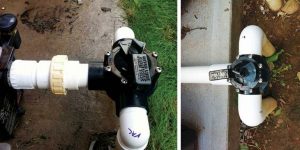
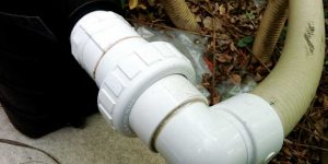
Incorrect (left): This system uses 38-mm (1.5-in.) pipe, sharp-bend street elbows, a union and a very short straight run into the pump. Correct (right): The plumbing was increased to 51-mm (2-in.) pipe, does not use sharp-bend elbows, and includes a straight run of rigid pipe to the pump intake.
Total dynamic head loss is defined as the overall increase in resistance to flow from friction. This can be broken down further into major losses (e.g. pipe friction) and minor losses (e.g. friction from fittings).
In a pool, the minor losses often can be greater than the major losses. Minor losses are usually not calculated, but rather estimated, at least from a design perspective. A designer/builder can attempt to calculate the total friction loss in the system, but this method will be subject to errors in estimation due to real world conditions. At best, calculations for TDH on a pool system should be considered a working estimate.
The easiest way to test TDH is to break it down into two sections—suction-side and pressure-side losses. First, multiply the pounds per square inch (psi) reading on the filter’s pressure gauge by 2.31 to determine the pressure-side friction loss. Then, to test the suction-side friction loss, install a vacuum gauge into the front winterization port on the pump. Multiply the vacuum (measured in inches of mercury [(inHg]) by 1.13 to determine the suction side friction loss. The total friction loss of the system is the sum of both figures.
Even after conducting this test, there is still a good chance for error in the calculation as it would only be an estimate of the friction loss in the system at that precise moment. Many factors will alter this calculated value, such as changes in the filter condition, orientation of any valves, or water velocity. It would be considered normal to estimate the total friction losses of a system for the purpose of pump and filter sizing as opposed to field testing these friction loss values.
From the perspective of a residential pool service technician, it is reasonable to estimate total head loss for a given pool system instead of attempting to calculate true values. Using a general guideline that inground pools range between 9 and 18 m (30 and 60 ft) of head resistance and above-ground pools between 4.5 and 9 m (15 and 30 ft) of head resistance. To make an accurate estimate, the factors that affect friction loss must be understood.
Water velocity
Choosing the correct plumbing fittings and valves, and more importantly, installing them in the proper orientation, will go a long way towards reducing turbulence in a plumbing system.
The faster water travels through a pipe the greater the friction losses will be. Conversely, the slower the water travels, the lower the friction losses will be. The rate of friction loss is not linear as water speeds increase. There is a soft maximum flow rate for each pipe size in excess of which the rate of friction increase rises dramatically:
- 38 mm (1.5 in.) = 144 litres per minute (lpm) (38 gallons per minute [gpm]) suction / 189 lpm (50 gpm) discharge;
- 51 mm (2 in.) = 235 lpm (62 gpm) suction / 322 lpm (85 gpm) discharge;
- 63.5 mm (2.5 in.) = 333 lpm (88 gpm) suction / 447 lpm (118 gpm) discharge; and
- 76 mm (3 in.) = 511 lpm (135 gpm) suction / 689 lpm (182 gpm) discharge.
These values are arrived at by following the guideline of not exceeding 1.8 m/s (6 fps) velocity on suction lines and 2.4 m/s (8 fps) on return lines. This basis for maximum water velocity exists not only as a safety standard, but also as a working standard for efficiency and longevity of plumbing systems and, therefore, has been widely adopted in the pool industry.
This introduces the concept of a working value for maximum water velocity. There is no true maximum flow rate for a given pipe size since increasing the pump power will increase the flow rate in any situation, at least to a certain degree. There is, however, a value to indicate the maximum flow rate beyond which there is a sharp decrease in efficiency as a result of an increase in the friction experienced from pushing the water through the pipes.
Turbulence becomes greater as the velocity of water increases, which has a direct negative impact on the circulation system’s efficiency.
Turbulence
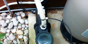
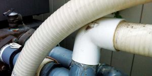
Turbulent water does not move efficiently; therefore, pool systems should be designed to minimize turbulent water flow. Choosing the correct plumbing fittings and valves, and installing them in the proper orientation, will go a long way towards reducing turbulence in a plumbing system. For example, a pump should have a long, unobstructed run of pipe into the suction-side port.
Having a serious flow restriction like a valve, or a sharp-bend elbow, directly in front of the pump inlet, will increase the rate of turbulence in the water as it enters the pump chamber. The smoothness of the pipe wall also contributes to the amount of energy lost to friction in a plumbing system. This is one reason why flex PVC is inferior to rigid PVC, as the striations in the pipe wall are a flow restriction. Pool systems that use multiple sharp-bend elbow fittings or fittings too close to the pump inlet should be altered to reduce unnecessary energy loss due to poor flow dynamics from turbulence.
Pipe sizing
Pool systems that use multiple sharp-bend elbow fittings or fittings too close to the pump inlet should be altered to reduce unnecessary energy loss due to poor flow dynamics.
The size of a pool’s plumbing lines will be the ultimate roadblock for how much water a system can move efficiently. With new residential-grade pumps on the market that have the ability to move 606 lpm (160 gpm) of water, it is easy to see how 38-mm (1.5-in.) pipe leaves much to be desired. To realize anywhere near the full potential of a high-volume pump, like many variable-speed pumps, the plumbing system should be 63.5 mm (2.5 in.) or larger on suction lines and 51 mm (2 in.) on return lines (if not larger). The current industry standard is 51 mm (2 in.) at most and this still severely limits the efficiency at which any system is able to operate.
When a powerful pump is installed on a system with 38 mm (1.5 in.) plumbing lines, or a system with multiple flow restrictions such as ball valves, sharp-bend elbows, or multi-port valves, much of the potential for energy efficiency is lost due to energy loss to friction at higher speeds. Designing the pool system to meet the turnover rate at a lower water velocity can actually maximize its energy efficiency.
Turnover rates
A turnover is the cycle of the entire water volume in a pool passing through the filtration system. Since the water returning from the filter mixes back in with the yet-unfiltered water in the pool, there is a calculation for determining how much of the pool water goes through the filter during each turnover: 63 per cent on the first pass, 86 per cent on the second, and 95 per cent on the third.
Theoretically, after the third turnover, the water in the pool has passed through the filter at least once. As a result, the ideal guideline for a residential pool is one turnover every eight hours or three turnovers every 24 hours. For example, for a typical 75,708-L (20,000-gal) pool, this would require 227,124 L (60,000 gal) to pass through the filter every 24 hours, which is 9464 litres per hour (lph) (2500 gallons per hour [gph]) and 158 lpm (42 gpm). Therefore, in this example, the minimum flow rate on this system would be 158 lpm (42 gpm).
Pump sizing
To determine pump sizing, the system’s minimum flow rate must be known—in this case, 158 lpm (42 gpm)—as well as the maximum flow rate to determine the system’s pipe size. Assuming the system uses a pipe size of 51 mm (2 in.) and has a maximum velocity of 1.8 m/s (6 fps) 235 lpm (62 gpm), the ideal flow rate for this system can be calculated by averaging the minimum flow rate and the maximum water velocity. In this example it would be 197 lpm (52 gpm). Assuming a total dynamic head of 15 m (50 ft), a pump capable of producing 197 lpm (52 gpm) at 15 m (50 ft) of total dynamic head pressure would be required.
Using the same size pool, except for this example it is using 38-mm (1.5-in.) pipe, would result in a maximum of 144 lpm (38 gpm) at 1.8 m/s (6 fps), while a minimum turnover of 159 lpm (42 gpm) is required.
In the field, if the pump has enough power, it will exceed the soft limit of 144 lpm (38 gpm); however, there will be energy lost in the increased resistance to flow in the lines. As the water velocity increases, the greater the friction loss experienced in the system. Therefore, to meet the turnover rate for this pool, the pump will not be operating as efficiently as it would if the plumbing was larger.
Filter flow rates
Having a serious flow restriction like a valve, or a sharp-bend elbow, directly in front of the pump inlet, will increase the rate of turbulence in the water as it enters the pump chamber.
Pool filters are rated with a maximum designed flow rate which should not be exceeded. Doing so can cause failure of the filter’s internal components, as well as poor water filtration. The pump’s flow rate needs to be less than the maximum design flow rate for the filter. Many new pumps can easily output enough water to exceed designed flow rates for pool filters, especially sand filters. Cartridge filters are much more capable of handling higher flow rates due to the lack of a multi-port valve, which can be a significant restriction to flow.
Improving flow rates on existing systems
There are many pump and filter combinations that can work on a given pool with the pipe size being a limiting factor. A pump and filter installation that can meet the turnover requirement for the pool, while not exceeding 1.8 m/s (6 fps) velocity, or the maximum design flow rate for the filter, is ideal. This is the reason why two-speed and variable-speed pumps provide such improved efficiency over single-speed pumps. The same can be said as to why more horsepower is not any better, either. For existing systems struggling to meet the pool’s circulation and filtration demands, the following changes should be considered:
- Re-plumb the equipment pad entirely using 51-mm (2-in.) pipe. This will reduce velocity as water travels through the highest concentration of flow restrictions. Even if the system uses 38-mm (1.5-in.) plumbing lines underground, reducing the water velocity through the equipment pad will have a net positive change on friction loss in the system.
- Allow for an absolute minimum of five times the pipe diameter in a straight run directly into the suction port and out of the pressure side of the pump. Elbow fittings directly into the suction side of the pump should be re-plumbed wherever possible.
- Replace all sharp bend (i.e. street elbow) fittings with sweep elbow fittings. Each sharp-bend elbow is a significant flow restriction and should seldom be used. Any interior fit-barbed fittings on the equipment pad should be replaced with glued slip connections where possible.
- Replace single-speed pumps with variable-speed pumps to allow greater control over flow rates and to experience a marked increase in system efficiency and electrical savings.
- Replace small/older sand filters with cartridge filters that are better suited to accommodate the flow rates provided by powerful pumps. This is especially important when a system has been retrofitted with a pump larger than the filter is rated to handle.
In the field it will not always be possible to meet ideal installation requirements. Still, it is important to understand the limitations of plumbing size, the nature of how friction loss reduces efficiency, and how to minimize these losses by removing unnecessary restrictions to flow. Understanding these principles will not only help to ensure pool equipment is sized correctly, but also has the ability to keep the water clear. Further, it will also be installed in such a way as to get the maximum efficiency and service life out of each system component.
This article was written by Steve Goodale and originally appeared on Pool & Spa Marketing [link].